Create Depth Map Step-by-Step
Here we'd like to introduce three ways of creating depth map.
- Create Depth Map in Photoshop (Extended Application: HomeBrew3D)
- Create Depth in 3DS Max (Extended Application: HomeBrew3D)
- Create Depth with Generative AI (Extended Application: HomeBrew3D)
1. Create Depth Map in Photoshop
It would be not the only way to create depth maps in Photoshop. However, according to the situations you may refer to the following examples to choose a best way. Or, you may combine these ways to create your own.
Create Depth Maps for Simple Objects
Most of time we’ll need to convert the 2D objects (i.e. commercial products, …) into the 3D objects. Then, the following is a typical example as the study case.
- Set up the Eye Point
There MUST be an “Eye Point” to mimic our eyes to view the 3D objects. Normally, this “Eye Point” is located at the right front of the 3D objects or the position of gray level 255. Later, with “Gradient Tool”, all the gradient gray levels will stop here.
Add a new layer (named as “Eye Point”) to draw a red cross as the eye point with “Line Tool” as follows.
- Analyze how many 3D Objects to be Contoured
First of all, we have to analyze how many 3D objects to be contoured according to the 3D scene of a 2D image. The more the 3D objects, the higher 3D quality would be.
We are going to contour the following 2D image into 4 pieces of 3D objects according to the basic requirements.
- Define the Gray Level
All the depth maps we are going to create will refer to their gray levels to respond their corresponding distances. As a result, when we have a 2D image to create its depth map, firstly we have to build a “Gray Scale” inside our mind so that we can refer to the levels in which the 3D objects are located around. We may take the “Gray Scale” as a look up table.
The following is an example to show us that there is “Gray Scale” of from level 000 (Far Side) to level 255 (Near Side) along with the perspective view (slanted an angle of around 45 degrees) of the 2D image.
- Contour the 3D Objects
With the “Polygonal Lasso Tool” in Photoshop, we can precisely contour the 3D objects which are going to be applied by gradient gray scale.
- Select “Polygonal Lasso Tool” to contour the 3D objects. Also, since the “Anti-alias” and “Feather” will cause gradient shading on the edge of depth map, that will affect (or distort) the image quality after rendering from the depth map. Please disable “Anti-alias” and “Feather” functions.
- Contour the first 3D object with the “Polygonal Lasso Tool”.
- Add a new layer for the contour and name it as “Object 1 (Gray Level 128)” according to the farthest position of this 3D object is located at around gray level 128 on the Gray Scale.
- With “Gradient Tool”, we can fill out the first 3D object with gray levels as required.
Step 1: Set up the foreground gray level as color code “128” as follows.
Step 2: Set up the background gray level as color code “255” for the “Eye Point”. Later, all the gradient target of each 3D object will stop here.
Step 3: Choose “Linear Gradient” of “Gradient Tool” and select “Foreground to Background” as gradient direction.
Step 4: With “Linear Gradient”, fill out the first object from the farthest position of the object to the “Eye Point”.
- Likewise, we’ll contour the other 3D objects with the “Polygonal Lasso Tool” and “Linear Gradient” as follows.
Step 1: Contour the second object with “Polygonal Lasso Tool”.
Step 2: Add a new layer and assign the gradient level 128 according to the Gray Scale in which the farthest position of this 3D object is located around.
Step 3: Set up the gray level. With “Linear Gradient”, fill out the second object from the farthest position of the object to the “Eye Point”.
Step 4: We’ll go on the next two objects.
Add a new layer and assign the gradient level 64 according to the Gray Scale in which the farthest position of this 3D object is located around.
Set up the gray level. Aim at the “Eye Point” and fill out the third object with linear gradient tool from the farthest position to the eye point.
Finally, we’ll contour the fourth 3D object.
Add a new layer and assign the gradient level 64 according to the Gray Scale in which the farthest position of this 3D object is located around.
Set up the gray level and fill out the fourth object with linear gradient tool from the farthest position to the eye point.
- When the depth map of each 3D object is well done, then we’ll need a gray level “000” to act as the background of these 3D objects.
- Finally, we’ll get the depth map as follows.
- Other Gradient Tools
For some situations, we can’t just use the “Linear Gradient” tool to create the gray levels for the 3D objects. Instead, we have to use other gradient tools like “Reflected Gradient”, “Radial Gradient”, … etc.
Split Color Channels into Grayscale Images
Step 1: Split Channels
Open the 2D image and select “CHANNELS” tab to split them.
Then, there will be three separated grayscale images generated as follows.
Step 2: Choose the most suitable channel
What we are trying to get the best depth map would be that the 3D object has the great gradient shading with the black background.
If so, then we’ll invert these grayscale images so as to get the black background. And, we can easily find the “Channel R” would be the most suitable one because it has the great gradient shading from dark to brightness.
Step 3: Then, we’ll use the “Dodge Tool”, “Burn Tool” and “Sponge Tool” to edit “Channel R” until it can meet our requirement as follows.
2D Image with Great Gradient Brightness
Step1: With “Image\Mode\Grayscale” function, we can convert it into a grayscale image.
Step 2: With “Image\Adjustments\Invert” function, then we can convert it into a depth map as we want. If necessary, we can do more contrast on it.
Process the “Fire” Image into a Depth Map
Since it is very hard to contour the 3D objects from a fire image, instead we can directly split the 2D image into RGB grayscale images and choose a suitable one for the depth map.
Step 1: Open the “Fire” image.
Step 2: Split the 2D image into RGB grayscale images. And, choose “Channel G” as the depth map.
Step 3: If necessary, we can use “Dodge Tool” and “Burn Tool” to improve the quality.
Process Branches of Trees into a Depth Map
Step 1: Open the image.
Step 2: Split the 2D image into RGB grayscale images. And, “Channel B” would be the best one for further processing.
Step 3: With “Image\Adjustments\Invert” function, we can convert “Channel B” to get the black background. Later on, if necessary, we can use “Dodge Tool” to add more dark (or brightness) to different branches.
Step 4: With “Filter\Blur\Gaussian Blur”, we can significantly eliminate the distant small branches and highlight the front ones.
Step 1: Open the image.
Step 2: Split the 2D image into RGB grayscale images. And, “Channel B” would be the best one for further processing.
Step 3: With “Gradient Tool”, we can fill the selected river area with the gray levels of from 000 to 255.
Step 4: With “Burn Tool”, we can make the fireworks little dark.
Step 5: With “Filter\Blur\Gaussian Blur”, we can significantly eliminate the distant small fireworks and highlight the front ones.
In additionally, PhotoShop 2021 (or above) has begun to provide the function of automatically creating "Depth Map". The following is how to use it.
Step 1:
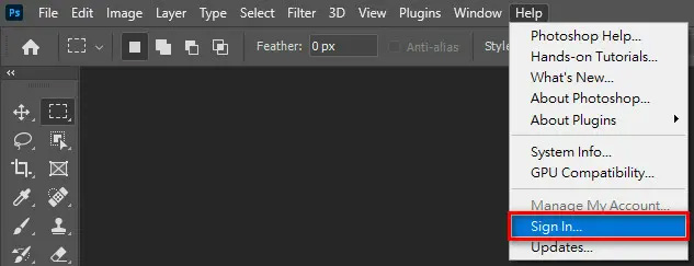
You must first log in to Adobe Creative Cloud; or apply for an account first and then log in.
In Photoshop, open a 2D image.

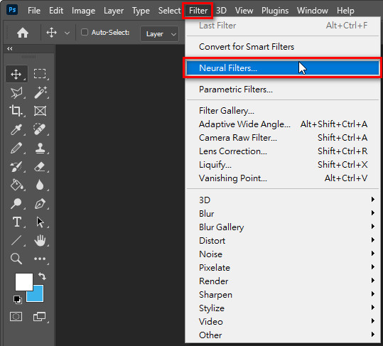
Click "Filter"\"Neural Filters"
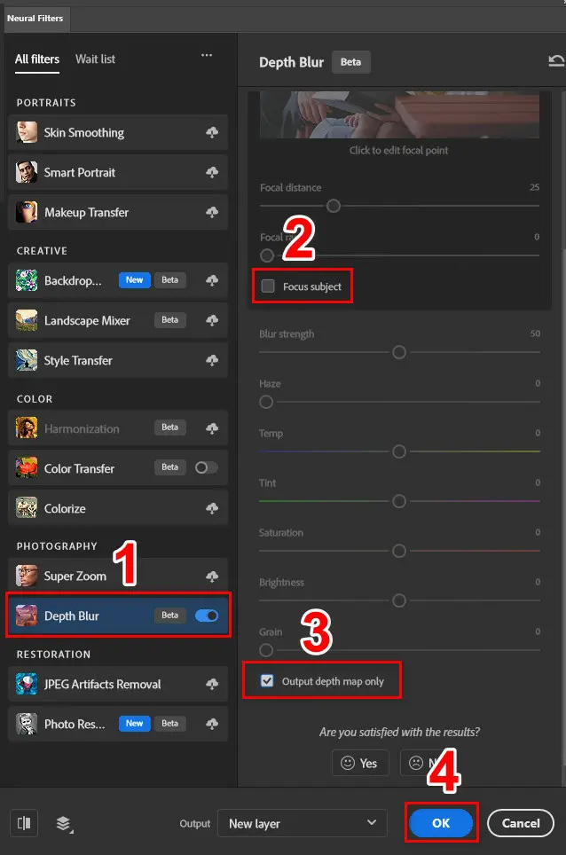
(1) Enable "Depth Blur" (2) Uncheck "Focus subject" (3) Check "Output depth map only" (4) Press "OK"
Automatically converted into a "Depth Map".

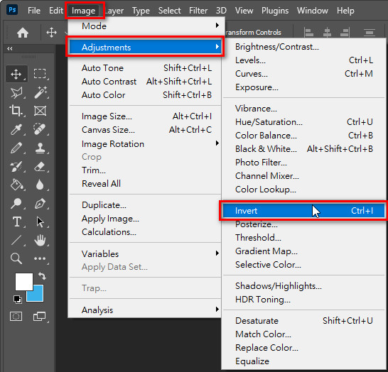
Click "Image"\"Adjustments"\"Invert": Invert the "Depth Map".
Final completed "Depth Map"
- When you have created the 3D scene, then please open the “Render” dialogue in 3DS Max command line for rendering it.
- Go to “Render Elements” in the “Render” dialogue.
- Click “Add” and select “Z Depth”. And, specify a folder to save the “Z Depth” (or Depth Map) in “BMP” format while rendering. Also, you have to specify the range for “Z Depth” according to your 3D scene.
- Later on, please select the camera and specify the minimum and maximum camera distance within the range of “Z Depth” as specified previously. For instance, you may specify 150 for “Near” and 450 for “Far” respectively so that they can be within the range (100 ~ 500) of “Z Depth” as specified previously.
- When you have checked “Show” in the “Environment Ranges” for camera distance setting previously, then besides the camera target plane it will add extra foreground and background planes to the camera view as shown below.
In order to get the best 3D depth quality, you should arrange the 3D objects (or models) inside the range between foreground and background planes.
If the 3D objects are closer than the foreground plane, then they will be set to the distance of the foreground when rendering because the maximum gray level “255” is located at foreground plane. Likewise, If the 3D objects are farther than the background plane, then they will be set to the distance of background when rendering because the minimum gray level “00” is located at background plane.
Note: “Background” plane will stand for the value “00” as the gray level while “Foreground” will stand for the value “255” as the gray level in the depth map.
- Go to “Common” in the “Render” dialogue. Make sure you have set up the necessary “Command Parameters” like “Time Output”, “Output Size”, “Render Output”, …etc. And, select the “Camera01” (for example) as the “Viewport” to start up rendering.
- When 3DS Max start to render your 3D scene, it will also output the depth map (or Z Depth) as required.
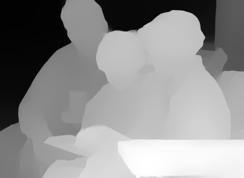
3. Create Depth Map with Generative AI
Currently, there is quite mature 3D technology on the market, which can automatically convert 2D images or videos into depth maps, and then render them into multi-view images or videos. The development of these technologies benefits from advances in deep learning and generative AI, making the 2D to 3D conversion process faster and more accurate.
The following are four AI tools currently on the market that can produce high-quality depth maps:
(1) Depth Anything V2: This is a website on Hugging Face that automatically converts 2D images into Depth Map images.
(2) Video Depth Anything: This is a website on Hugging Face that automatically converts 2D videos into Depth Map videos.
(3) Quick Depth: This is a plug-in software for After Effcts that can quickly and automatically convert 2D images (videos) into Depth Map images..
(4) Depth Scanner:This is a plug-in software for After Effects that can quickly and automatically convert 2D images (videos) into Depth Map images..
After the depth map is completed, the next step is to render it into a "multi-view 3D" image (or video), and then further display it in "Glasses-Free 3D". There is currently an i-Magic3D software that can help us use 3D lentcular lens that are easily available on the market, and any OLED/LCD panel, laptop, tablet, Android or iPhone to build our own "Glasses-Free 3D Display". Please refer to 3D WorkShop for details.